Chain brake & Husqvarna 55XP triobrake repair
This article reviews the 10 Chainsaw safety features and details common faults and repairs to the chain brake system of a Husqvarna 55XP Triobrake.
Chainsaw safety features are at the heart of the entry-level qualifications for chainsaw maintenance & crosscutting. As well as their names & location on the saw, a more detailed understanding of their composite components, condition checks, likely wear or deterioration and, in practical use, when starting, testing and crosscutting material is required. The features are:
- Rear handguard
- Stop switch
- Throttle interlock
- Safety decals
- Vibration reduction mounts/system
- Chain catcher
- Chain brake & front handguard
- Exhaust
- Chain & guide bar combination offering a reduced kickback
- Scabbard
The chain brake is arguably the primary chainsaw safety feature; it can help protect trained operators when they activate it before starting, releasing a hand or moving – pre-emptive safety in the event of an uncontrolled throttle opening or fall. Likewise, in the event of kickback the, left-hand forces the brake on, combined with a disciplined stance and head position, will protect operators.
It also protects those with no training or knowledge in the event of kickback that activates the brake via the inertia system - the chain is stopped without the hand touching the activation lever or guard.
The Husqvarna Triobrake also offers an activation option on the rear or right hand. We’ve found this useful when the saw is turned engine up, and an attempt is made to use the saw without good body position. The wrist angle makes brake engagement more likely, forcing a change to a better position.
Basic chainsaw units have recently been updated as part of a periodic review of City & Guilds Forestry & Arboricultural units. This has resulted in a less cluttered assessment schedule for the basic chainsaw maintenance & crosscutting and the felling trees under 380mm units 003920/ 003921.
How it works
The chain brake is powered by a strong spring, which causes a thin metal band to clamp tight around the bell housing; this is linked to the drive sprocket and chain and stops the chainsaw chain dead upon activation. When the handle is pulled back to release the chain, the spring is re-set via a trigger and lever system ready to be deployed the next time.
The handle and front handguard should move easily and work from any hand position, be secure and free of cracks. Mounting screws and retainers can sometimes come loose or seize up, and the return spring can fail in a Stihl machine; this can be spotted if the chain brake fails to maintain a favourable position and flops about.
The chain brake function must be verified before use in the pre-use checks and then monitored in use; this is the first check made following a cold start.
In a workshop setting the band needs to be cleaned of oil and debris, it may then be visually inspected for damage, noting the following points;
- Cracks
- Scoring
- Heat damage
- Thinning or material loss
- Shape distortion
With an outboard clutch, the band is accessible, and the above checks can be completed without removing additional components. Although only the outside edge of the band is visible on an inboard clutch machine, removing the bell housing can improve visibility, or complete removal may be desirable.
The trigger mechanism and spring benefit from a periodic clean but generally don’t fail.
In a training context, the chain brakes get a lot of use and sometimes abuse; this can shorten the normal life of the bands. In addition, the 550XPs typically fail at the 180-degree bend adjacent to the screw that holds the spring mount.
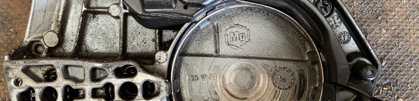
They are easily fixed by removing the plastic cover on the side casing and carefully releasing the spring. Use gloves & eye protection and prise the spring out whilst covered with a cloth. The mechanism then can be wriggled clear of the mounting pin and band end cut out.
Release the band screw fixing, clean the trigger mechanism if required and replace the band. Re-fit into the side casing and then use a medium-sized flat screwdriver to compress the spring and slot it into the housing when sufficiently compressed. Maintain pressure on the spring as the cover is replaced. This will only be possible with the band set to a closed position, so the final job is to release this and re-fit the side casing.
This situation can also result from side casing removal without first releasing the chain brake with the band clamped to a smaller diameter. It then will not go back on and is one of our frequent novice maintenance errors.
Remove the guide bar and chain and slide the side casing on at an angle to allow the chain brake activation handle to mesh with the trigger mechanism, maintain pressure as you pull the chain brake back. If this method doesn’t work, remove the clutch and position the side casing squarely onto the studs and release.
